
A new connection between a precast abutment wall and a cast-in-place foundation was developed for rapid construction of bridge abutments. The connection was developed at the University of Iceland with assistance provided by structural designers, a precast concrete fabricator, and the Icelandic Road and Coastal Administration
Bridge construction frequently leads to traffic delays, which incur costs that can be measured in time, money, and wasted fuel. Therefore, road administrations are seeking methods for accelerating the construction. This is often referred to as Accelerated Bridge Construction, or ABC. Several strategies for ABC use administrative techniques, and/or incorporate inventive financial incentives, while others have relied on new building practices to minimize the duration of on-site work.
The use of precast concrete represents a promising technology for ABC and has been successfully used for bridge piers in both non-seismic regions and seismic regions. Connections are typically made at the beam-column and column-foundation interfaces to facilitate fabrication and transportation. For structures in seismic regions, those interfaces represent the locations of high-bending moments and shears. Designing connections for both ease of construction and seismic resistance is a daunting challenge.
Abutment Connection Concept
The concept is referred to as a “wet” socket wall connection. It is demonstrated in Figure 1. The construction sequence is as follows: a precast (pc) wall element is fabricated in a controlled environment with a roughened outer surface in the wall region that will eventually be embedded in the foundation. Also at the bottom, the pc wall has wide horizontal ducts that allow top mat rebars to run through the wall to provide moment resistance. The inner surface of the ducts is rough. The foundation is excavated, the formwork is made, and the bottom reinforcement mat is tied. The wall element that has been transported to the site is then set, plumbed, leveled, and braced. The top reinforcement mat in the foundation is fitted through holes in the wall element, and the foundation is cast.
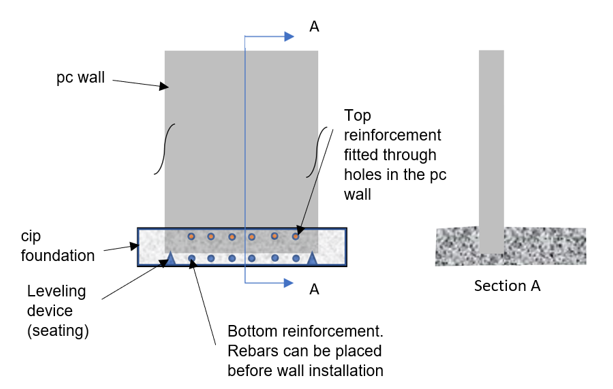
Figure 1. Socket wall connection concept
In comparison with conventional cast-in-place construction, the primary advantage of this system is construction speed; a foundation and an abutment wall can be built in a little more time than is needed to cast the foundation alone. Other advantages include avoiding any problems fitting up bars in vertical sleeves or ducts that would be encountered in setting the precast element on top of a cast-in-place foundation with starter bars and no protruding reinforcements on the wall element when it arrives on site that are vulnerable for transport and erection of the wall.
Tests
Two scaled (63%) test specimens were constructed and tested out-of-plane under quasi-static displacement-controlled one-sided lateral loads. Figure 2 shows the test setup.
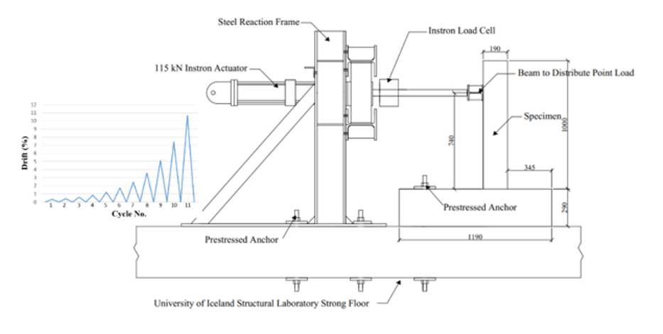
Figure 2. Test setup
The first specimen served as a reference specimen (“Cast-in-place Wall”) and was detailed according to current standards (e.g., Eurocode 0, Eurocode 2, and Vegagerðin Bridge Design Manual). The second specimen was the new connection and detailed according to the same standards (“Precast Wall”). Tests showed that the wall connection transferred loads from the abutment wall to the foundation successfully, and the construction of the socket connection indicated that field deployment would be simple. Figure 3 shows the tests specimens loaded at load Cycle No. 8.
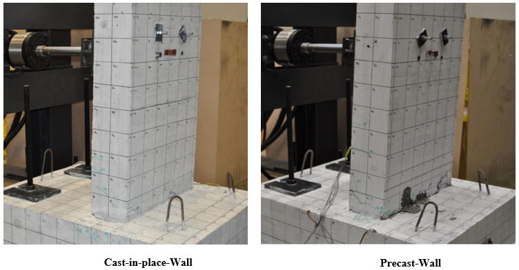
Figure 3. Specimens at peak displacement (target drift ratio 3.57% – load cycle No. 8)
Implementation
In North Iceland, a road reconstruction project is underway that includes the construction of a new bridge. The new bridge is a single-span design with a length of 9 meters and a width of 10 meters. To accelerate construction, the design team decided to implement the socket wall connection in their design. Given the substantial size of the abutment, the abutment wall was divided into six precast wall elements for ease of transport. Figure 4 provides a schematic plan view and elevation of the abutment design. This bridge project will provide an opportunity for the researchers to evaluate the time savings on-site relative to cast-in-place construction.
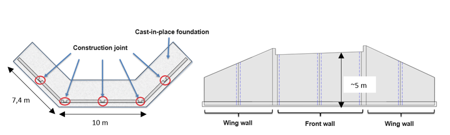
Figure 4. Plan view (left) and elevation (right)
Link to summery report (in Icelandic): https://www.vegagerdin.is/vefur2.nsf/Files/NR_1800_931_THroun_nyrrar_tengingar_milli_forsteypts_stopulveggjar_og_stadsteypts_sokkuls/$file/NR_1800_931_%C3%9Er%C3%B3un%20n%C3%BDrrar%20tengingar%20milli%20forsteypts%20st%C3%B6pulveggjar%20og%20sta%C3%B0steypts%20s%C3%B6kkuls.pdf
Link to a conference paper: https://link.springer.com/chapter/10.1007/978-3-031-32511-3_159
This research was funded by the Icelandic Road and Coastal Administration Research Fund
Ching-Yi Tsai – Research Scientist – University of Iceland
Ólafur Sveinn Haraldsson – Head of Research Department – Icelandic Road and Coastal Administration
Bjarni Bessason – Professor of Civil Engineering – University of Iceland

Franz Sigurjónsson – Bridge Engineer – EFLA Consulting Engineers


Follow us: